CGGC and GIP lab project
CS faculty, Technion

Triplanar mapping
In order to achieve the desired effect from the “Matrix” movie, our application should include two important parts, the first one being scanning the real world space and building the appropriate 3D model in the scene, and the second one - implementing the shader itself, basically drawing the digital rain animation with ShaderLab/HLSL code that Unity uses. The final step would be just applying the shader to the generated mesh, but this is where the main problem was lying - you just can’t use a regular shader with the mesh that LiDAR generates. The meshes that this scanner generates are very good both in terms of building time and precision, the best that we have achieved. Hence, to preserve the ability to use LiDAR and still be able to come up with something that recalls the original film in the shader itself, we needed to deepen our knowledge in the coordinates mapping in 3D.

When we want to create a shader in the traditional meaning, we basically create something that replaces or modifies the texture of a 3D object. So, for the simplicity of the explanation, let’s assume we have a simple 3D cube with a mesh, and we want to apply a very simple image texture to it.
As we can see after a few second of looking at the picture, the main problem to solve is how to apply a flat 2D image on 3D object with an already complicated form (even though it’s just a cube). Which edges of the cube should display which parts of the original texture image?

Every mesh of a 3D object has vertices - that’s how we create complex shapes in 3D. So, the proposed solution is to try to cut and flatten a 3D model like an “origami” and lay out the resulting pieces on a texture. After that, check where the original vertices are on the resulting flat plane. New coordinates on that plane are called u and v - because x,y and z are already used in our original 3D space.


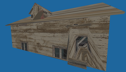
While this may seem like a pretty good intuitive solution, obviously there are some problems with it - i.e. is it always feasible to calculate and store these coordinates? For example, for any large scale 3D scene that includes real-world landscape frequently there is a need to texturize terrain, water or sky. Especially in case of terrain, it is a very large shape with a lot of details, such as dumps, mountains, caves, etc. If we were to use UV-mapping, we would have permanently stored coordinates for every point on the terrain mesh. Obviously, this is a lot of information to store (see image on the left).
Not only this approach requires a rather great amount of resources, sometimes it does not provide us with the best results.

There are alternative techniques to use instead of directly storing uv coordinates in all of the vertices. Using these techniques in the appropriate cases not only reduces amount of memory needed for storage, but also applies the original texture on the model with better precision and overall look. One of these techniques is called triplanar mapping. It is specifically useful with working with large scale surfaces like terrain or spheric shapes because it maps the texture seemingly without stretching and seams in the texture. The main thing is - this mapping solution doesn’t require us to keep any pre-calculated uv coordinates at all!
So, what essentially is triplanar mapping? In our previous case, the uv coordinates that were stored in the model vertices directly pointed us where to go and where to get a certain polygon from the texture image. But now, assuming that we only have world position of a polygon (our usual x, y and z), we try to look at this polygon from the directions of X, Y and Z axes and try to approximate the uv’s from there. Formally speaking, we use three projections of the world space coordinates vector on the orthogonal planes and then try to blend them into a weighted average and that’s our uv coordinates.

Now, let us run shortly through the math of all of this. To project a vertex on the three standard planes is very simple - we just need to reduce one coordinate for the each projection. Then, we can use normal values almost directly as weights because they essentially tell us to which direction the polygon is turned more. That is exactly what we need, for example if the normal vector is pointing to the Z direction, the resulting color will be very heavily consisted of the XY projection. Hence, we just normalize the vector and combine the resulting values in a weighted average.
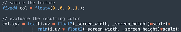
Previously, our shader consisted of two consequent calls to functions rain() and text(). Now, we just need to to do the same for three projections and blend the result together.
Before
After

As we can see, the number of the function calls has tripled, but in return pre-stored uv’s are not needed anymore. And now we can use our shader with the LiDAR.